The Breadboard & GPIO Field Guide

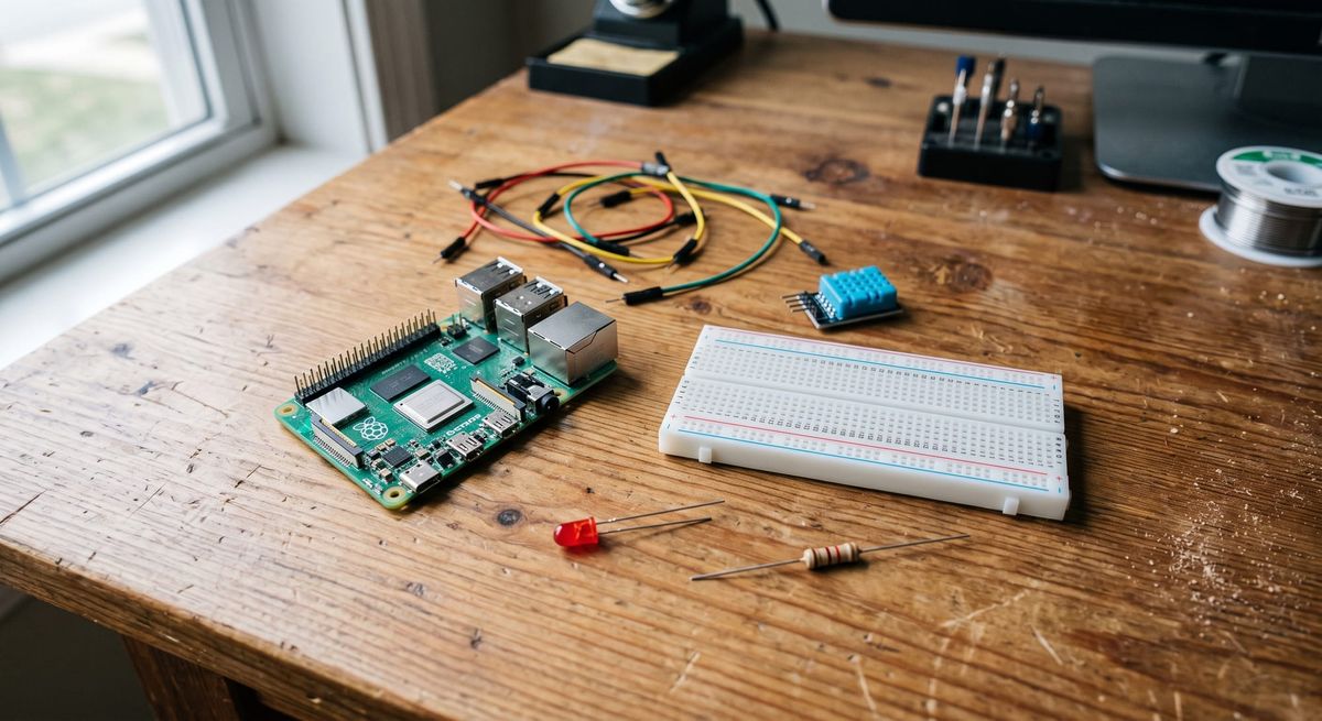
A hands-on reference from the iron-lab bench — how a breadboard, a GPIO extension board, and the Raspberry Pi's 40 pins actually fit together. Everything below is interactive: hover on desktop, tap on mobile.
1 · What a breadboard is, under the plastic
Inside the plastic there are two kinds of metal spring-clip strips, and everything about breadboard wiring follows from their shape:
Terminal strips (the middle): each little clip is 5 holes long and sits perpendicular to the board's long axis. That's why A5 B5 C5 D5 E5 are one electrical point, while A5 and A6 are strangers. There is no "east–west vs north–south" rule in the abstract — the rule is: the 5-hole group is the connection; the direction it runs depends on how you've rotated the board. Find the row of 5, and you've found the node.
Bus strips (the rails on the edges): one long clip that runs the full length of the board, parallel to the long axis. The red-striped one and blue-striped one are just two independent long wires — the colors are paint, not electronics.
The center channel is a wall. No clip crosses it. E5 and F5 are unrelated. It exists so a chip (or a T-cobbler) can straddle it with legs on both sides without shorting its own pins together.
2 · What the GPIO extension board is
It is just 40 wires with labels. No chips, no logic. The ribbon cable carries all 40 header pins from the Pi; the T-shaped board fans them out into two rows of pins that straddle the center channel — exactly like a big chip. Each of its pins lands in one hole, which means:
The printed labels (3V3, GPIO17, SPIMOSI, ID_SD…) are the names of those 40 wires. A label like SPIMOSI doesn't mean "special mystery pin" — it's GPIO10 wearing its job title. See section 4.
3 · Jumper wires
A jumper is a wire with pins on the ends — nothing more. Its whole job is: take one electrical point and extend it to another electrical point. Plug one end into any hole of a 5-hole group, and the other end's group joins the same node.
| Type | Ends | You use it for |
|---|---|---|
| Male – Male | pin → pin | Breadboard hole to breadboard hole (the common case with an extension board) |
| Male – Female | pin → socket | Breadboard hole directly to a Pi header pin or a sensor's pins (no extension board needed) |
| Female – Female | socket → socket | Pi header directly to a sensor module's pins, skipping the breadboard entirely |
A DHT11 or PIR sensor can be wired with three F–F jumpers and no breadboard at all. The breadboard earns its keep when a circuit needs a component in series — like an LED plus its resistor.
4 · The 40 pins — what the labels mean
Hover or tap any pin. Blue outline = currently wired in my lab.
The four families
| Family | Pins | What it is |
|---|---|---|
| Power out | 3V3 (×2), 5V (×2) | Not controllable, always on. 5V comes straight from the USB-C supply; 3V3 is regulated by the Pi. Used to feed sensors that need supply power (my PIR and DHT11 run off these). |
| Ground | GND (×8) | All eight are the same wire internally. Eight of them exist purely for convenience. Every circuit must return to one of these — current flows in loops: out of a pin, through the component, back to GND. |
| GPIO | GPIO2 – GPIO27 | The controllable pins. Software drives them to 3.3 V ("high") or 0 V ("low"), or reads which of the two a sensor is presenting. The numbers are BCM/GPIO numbers, not physical positions — GPIO4 lives at physical pin 7. |
| Labeled GPIO | SDA1, SCL1, TXD0, RXD0, SPIMOSI, SPIMISO, SPISCLK, SPICE0/1 | Ordinary GPIOs that also have a built-in second job (a communication bus: I²C, UART, SPI). SPIMOSI = GPIO10. If you're not using that bus, most can be used as plain GPIOs — but with 17 unlabeled ones available, just don't bother. |
| ID_SD / ID_SC | physical 27, 28 | Reserved for the HAT identification EEPROM. Treat as off-limits. This is the one label that genuinely means "not for you." |
5 · When do the rails earn their keep?
The rails are a distribution convenience, nothing else. The Pi gives you a handful of GND and power pins, but many circuits want to touch ground. So you spend one jumper turning the blue rail into ground:
That's the pattern on my own board: both LED resistors end at the blue rail, and the rail is grounded once. Without the rail you'd need a separate path back to a GND pin for every single component.
The red + rail is the same idea for supply power — jumper it once from 3V3 (or 5V) and any component needing power taps the rail. Use it when multiple things need the same supply. One discipline: a rail carries one voltage, ever. If you put 5V on a red rail, label it in your head as the 5V rail and never tap it toward a 3.3V-only device.
| Situation | Rails? |
|---|---|
| One LED + resistor | Optional — could return straight to a GND pin's column. Rail keeps it tidy. |
| Two LEDs, one sensor, all need ground | Yes — this is the textbook case. One GND jumper, everyone shares. (= my board) |
| Several 5 V sensors | Red rail from 5V pin, blue rail from GND, each sensor taps both. |
| Nothing shares a node | Skip them. Rails are optional plumbing, not a requirement. |
6 · Reading a real LED circuit with all of the above
Trace the loop: current leaves GPIO5 when software drives it high → through the jumper into the LED's column → through the LED → into a private column shared only with the resistor → through the resistor to the ground rail → back into the Pi via the GND pin. Five holes per column is what lets each hop work; the private middle column is what forces current through the resistor instead of around it.